How To Set Up Your Engineering Lathe
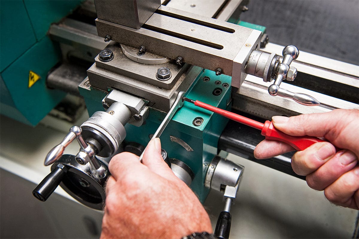
When working with an engineering lathe, everything boils down to accuracy. Whilst a few millimetres here and there in woodworking may not be an issue, it would be a cardinal sin to be even 0.5mm out in metal working.
With that in mind, to get the best performance from your machine tool, it's important that it's set up and maintained within specific tolerances.
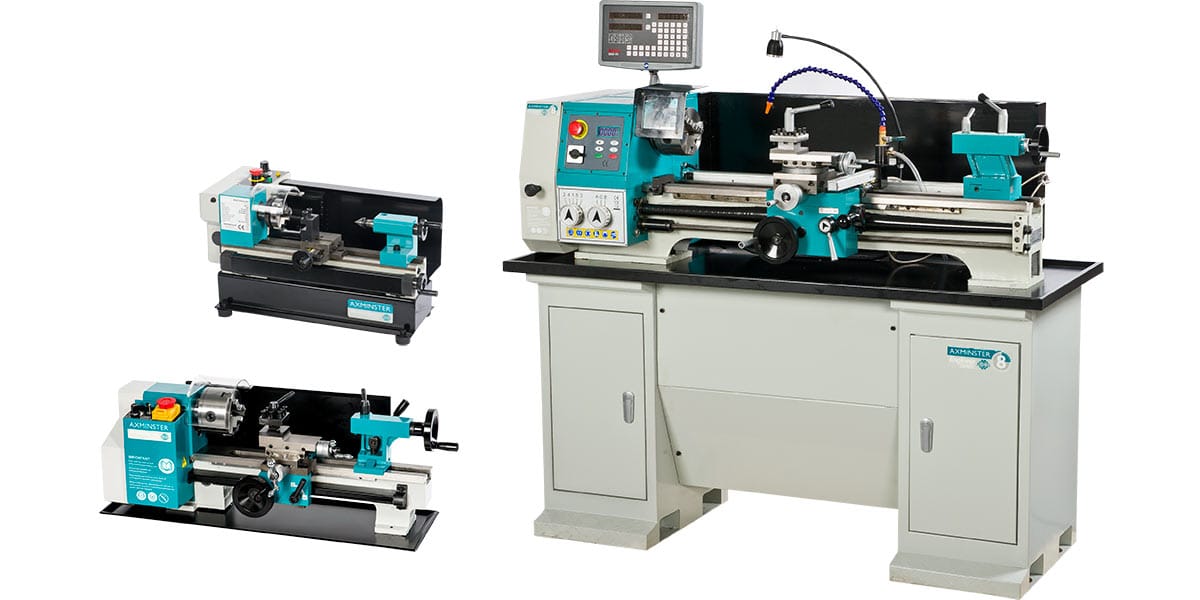
The Engineering Lathe
On a machine such as a lathe the movements need to be set, so that the slideways can move freely but show no undue slackness. So, after initial commissioning, your machine requires a quick check to ensure all movements are functioning correctly.
On the engineering lathe, there are three main slideway movements to maintain;
- The top slide
- The cross slide
- The saddle
Additionally there is one main rotary movement, which is the machine spindle.
The Adjustments
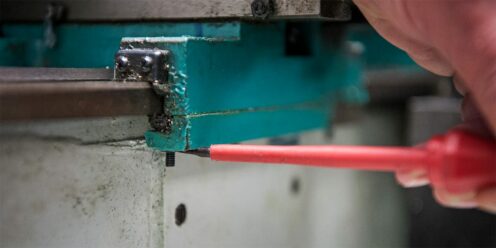
The slideways are adjusted using 'jib strips'. These are parts of the slide that can be moved to reduce the clearance by means of adjusting the screws. To achieve the correct clearance, the adjusting screws are tightened until stiff, then 'backed off'. This will achieve a slight drag without making the machine hard to use.
Top Slide
Most smaller machines have a row of screws and locknuts along the side of the slide. These are adjusted in turn as the slide is operated, ensuring the stationary part of the assembly is located under the relevant screw. This is so the jib strip is set parallel along it's length.
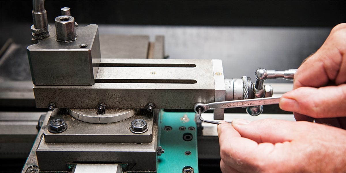
Larger machines may have a tapered jib that is pushed along a corresponding track, which reduces the slide clearance in a parallel motion. One screw is loosened and another tightened by using very small increments of about half a turn.
Top Tip!
After each adjustment, check the handwheel motion to ensure that the drag is constant along the whole slideway.
Cross Slide
The adjustment of the cross slide is the same method as used on the top slide. Here the screws are located on the right hand side of the slide, generally with not as many of them, due to the longer contact area and subsequent added stability.

The Saddle
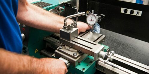
Out of the three slideway movements, this is the most difficult to adjust. This movement is controlled by holding the saddle down on the machine bed using sheer plates. These are bolted to the underside of the saddle and then hook underneath the bedways, preventing the saddle from lifting. You can check the accuracy of the saddle, by using a dial gauge and applying force on the front and back to see the movement. (see image below)
The methods of adjustment vary from machine to machine, with the larger machines having taper style jib strips and the smaller machines having screws or locknuts. These may also require hand fitting to remove metal from their clamping faces to reduce the running clearance.
Because of the sheer plate location, any adjustment is very awkward. Both the front and rear plates require adjustment to prevent the saddle from lifting. This is even more important on the smaller machines as they have lighter saddles and consequently less mass to resist the cutting forces. The clearance between the underside of the bed and the sheerplates should ideally be 0.01 - 0.02mm (1/2 to 1 thousandth of an inch).
Machine Spindle
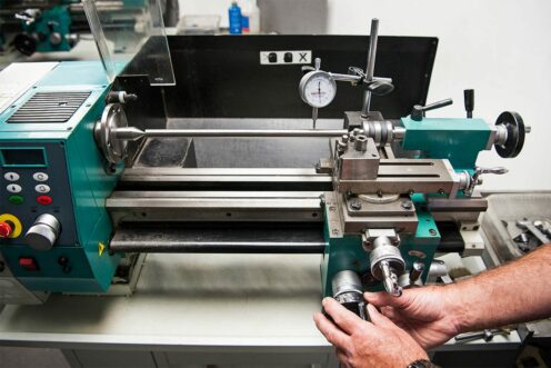
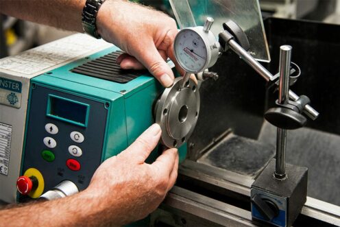
The main spindle bearings should only be adjusted if there is measureable 'play' in the spindle. This should be checked using a dial gauge and can be done on the spindle itself, which is the most accurate way. It can also be done on the chuck, if one is already attached but this will be less accurate.
It's also good to check the spindle further away from the headstock. If the spindle at the headstock is only very slightly out, this will be exaggerated the further away you get.
The bearings are factory set and so very hard to adjust. It should only be attempted if you are confident that the correct pre load can be achieved. If they are too tight, the bearings life will be greatly reduced. With this in mind, it's best to speak to the servicing team of your supplier to get this issue resolved.
Machine Drive Leadscrews
On most machines, the leadscrews and their corresponding drive nuts will have some provision for reducing backlash.
Lost motion in any movement can form between the leadscrew thread and the drive nut. Some machines have an adjustment screw that 'spreads' the nut to take up the slack in the thread. Any adjustment must be carried out at the ends of the leadscrew that will have least wear.
The other place that can cause lost motion is in the handle bearing housing. If the leadscrew isn't positively supported it can move back and forth when the handwheel is rotated. In most cases this clearance can be reduced by adjusting the nuts that hold the handwheel in place. Adjust until the movement begins to feel secure without being too tight.
These adjustments will help you to get the most from your engineering lathe. Remember for future use and maintenance, use the correct lubrication on a regular basis. This will not only prolong the life of the machine but also keep it's performance at the optimum level.


