
How To Build A Power Tool Table: Part 1
When I worked in the trade some years ago, I was somewhat surprised to see that all the makers were equipped with two benches, the first being more or less a standard woodwork bench, the second being an 8 x 4’ sheet of mdf on a pine frame which served as an assembly and gluing up table. When I subsequently built my workshop some years later, I adopted the same sort of idea; a cabinetmaker’s bench to make the components and a similar sized table to assemble them.
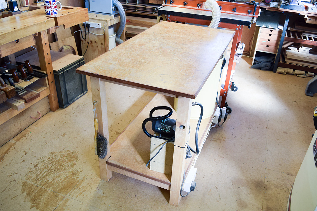
The pic above shows the bench I built using 60mm square beech legs and a respectably sized under-framing, complete with an 18mm ply top and storage shelf on the underside. The top was additionally covered with hardboard and heavily waxed to prevent glue adhesion.
I did, however, make a serious mistake in that I added a cross braced rail using a halving joint which had the overall effect of reducing the load capacity of the long upper rails. The result of this error was that they eventually bent producing a bowed top!
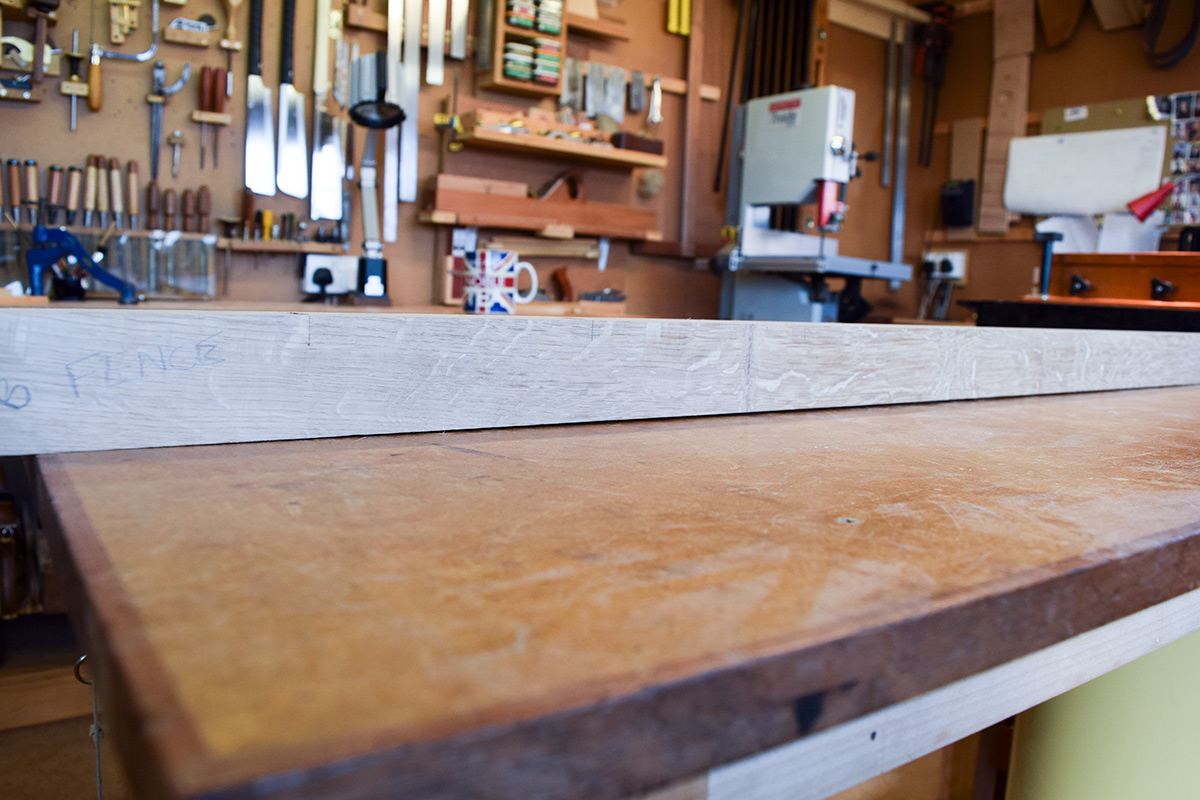 The pic above shows just how much... around 2.5mm in the centre which doesn’t sound too bad but it’s critical to have a dead flat surface when assembling a framework. A cupped or bowed surface compounds the whole thing and could potentially make an already complicated gluing process that much more tiresome!
Fed up with the deficiencies of the original, I decided to make a new one, as shown below.
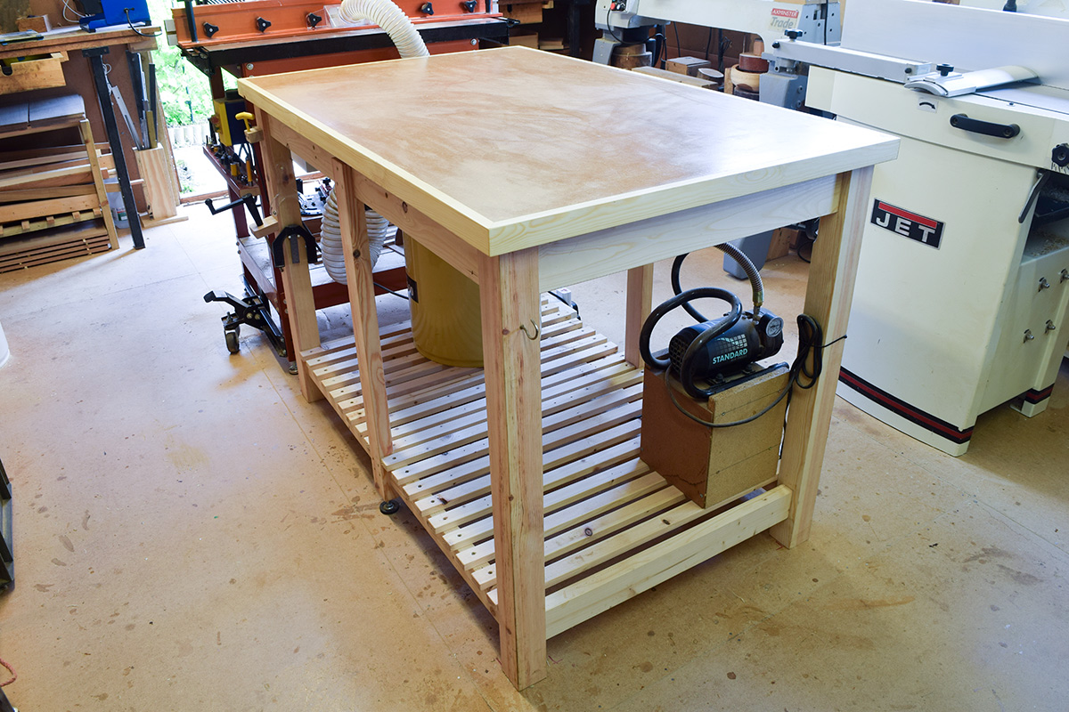
This is about the same size and uses roughly a quarter sized sheet of mdf for the top, but there’s a very significant difference as this surface is only a cover.
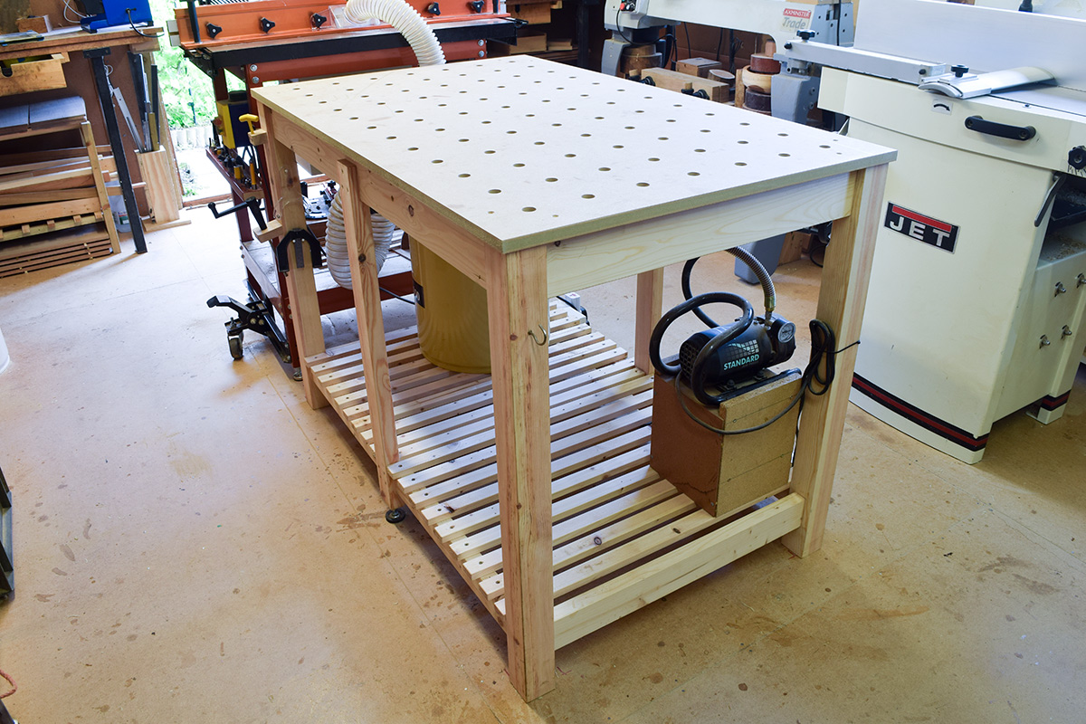
Removing it reveals another one underneath; a grid of 20mm holes to perform exactly the same function as a Festool MFT/3 table which can be used with our excellent stainless steel, Veritas Parf Dogs. This top wouldn’t be possible to make without the recent introduction of the UJK Technology Parf Guide System developed with Axminster by Peter Parfitt. Using the jig to construct the Power Tool Top will be shown in far greater detail in subsequent articles.
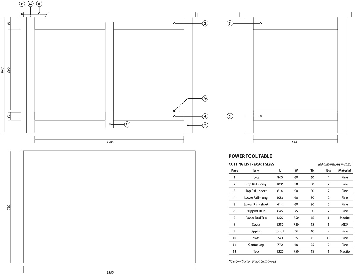
The Framework
The first task was to produce a couple of detailed working drawings, the first showing a quarter of the table on a scale 1:1 which allowed for the precise location of the framework rails and legs to be determined underneath the top. The second drawing was on a 1:5 scale with three elevations and showed overall dimensions, constructional details and a cutting list with exact sizes in mm.
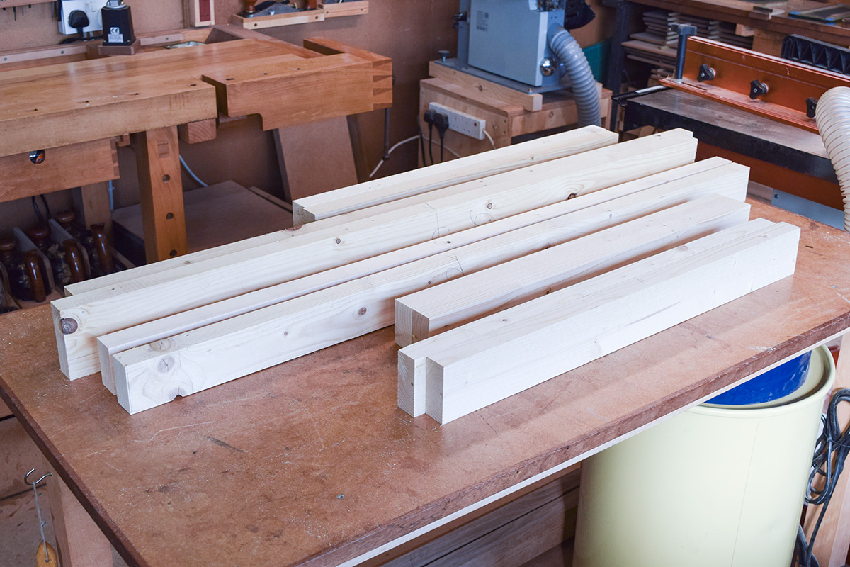
I already had sufficient, secondhand but very dry timber for the rails which are shown machined to size (but not cut to length) on the original assembly table.
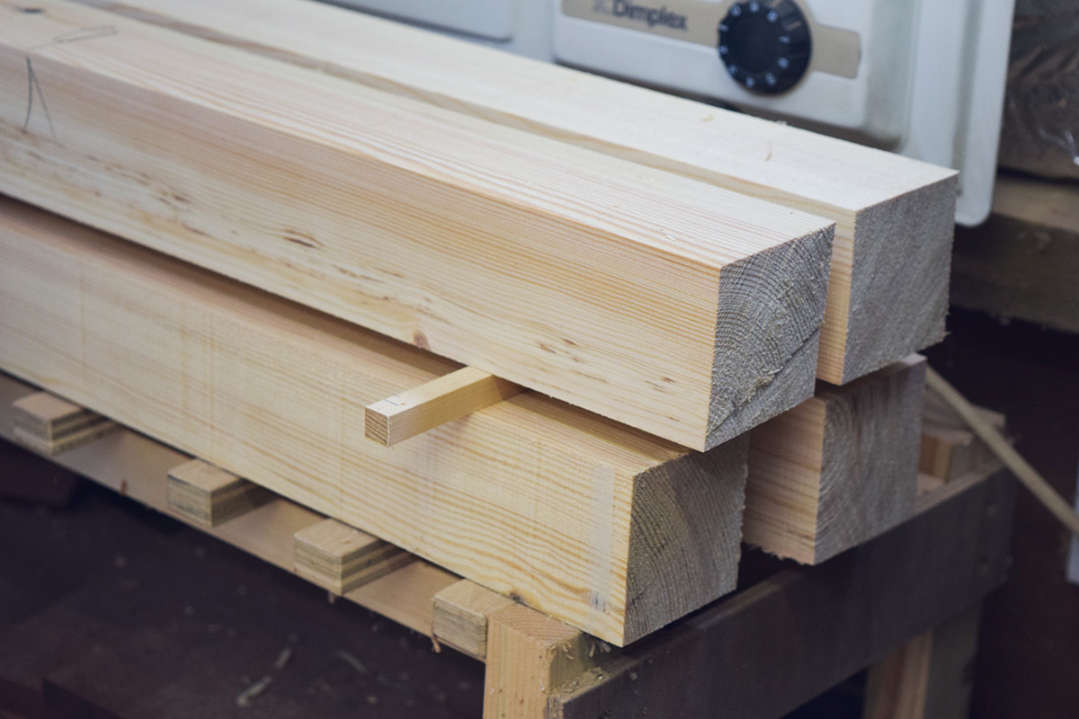
The legs were rough cut from new, good quality, joinery grade pine and have been left over size to allow for any possible movement before final machining to size.
Any method of construction could be used for this project including traditional mortice and tenon joinery, large Dominos or 10mm dowels, which is my preferred method using the Dowelmax system.
The following two articles will look in more detail at the construction of the framework.


Hello Rob,
In the cutting list of the Power Tool Table I see the medite top mentioned twice, parts number 7 and 12. Is this done on purpose or an error?
Btw I enjoyed reading your 3-part article on this subject.
Hello and thanks for your comment. That of course is an error as No.12 in the parts list refers to the top...item 7 doesn't appear on the drawing. Good to hear also that you enjoyed reading about the build, thus far it's been a very useful piece of kit in the workshop and I can also confirm that the matrix of holes made with the UJK Tech. Parf Guide System is absolutely spot on.
It was your article which made me decide to buy the Parf Guide System.