Mission Style Clock Case | How To
What you'll need
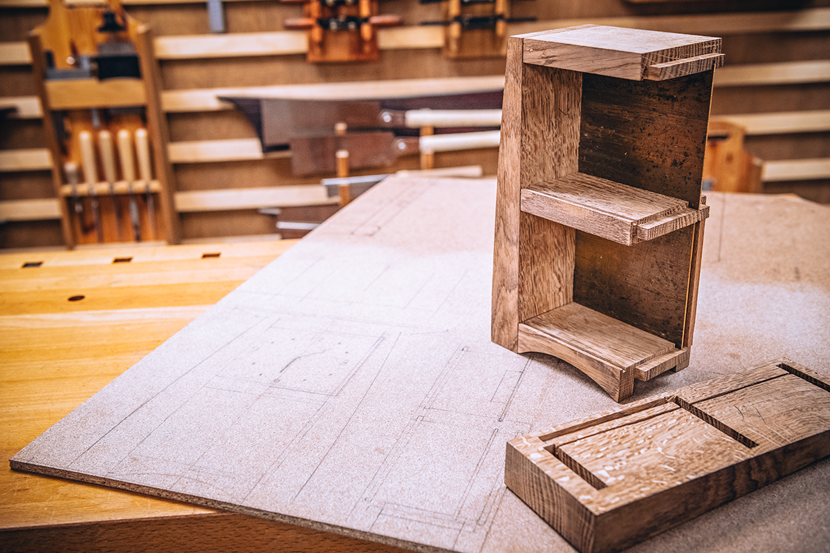
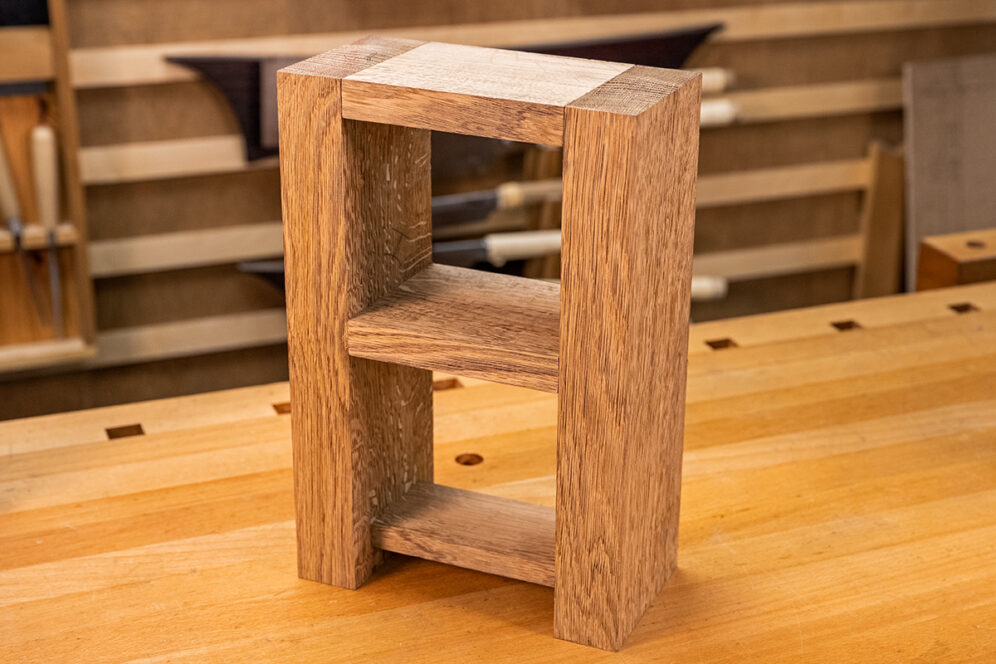
A mission style clock case is a simple and elegant clock design that forms part of the arts and crafts movement. This style of clock is often made from oak with the design focusing on horizontal and vertical lines and flat panels, which accentuates the grain of the oak.
In this Woodworking Wisdom, Jason will show you how to make a simple clock case using traditional mortice and tenon joints, before Ben takes over to create a beautiful copper face and decorative panel insert. Watch our Woodworking Wisdom demo, or follow our step by step guide below.
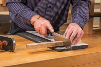
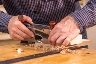
Prep your timber
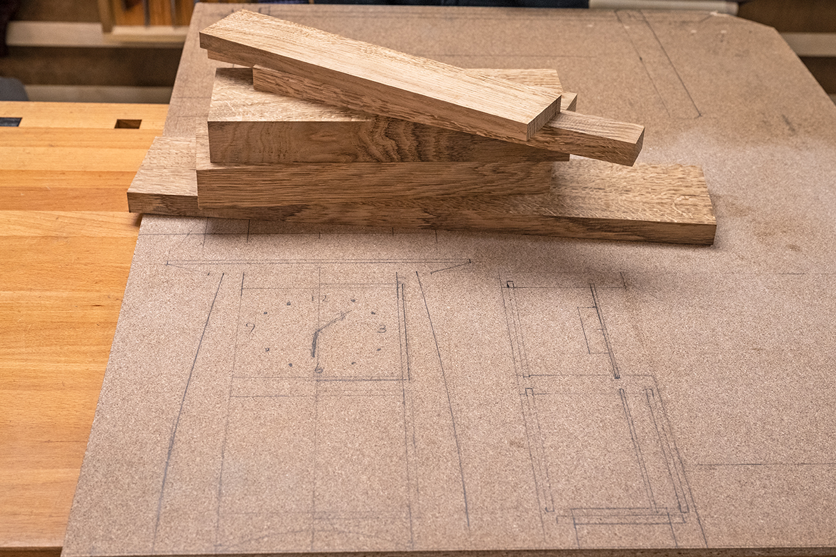
Begin by sketching out your design on a scrap piece of MDF - this will help you decide the sizes and dimensions of your finished clock. Once this has been decided you can machine your timber to size.
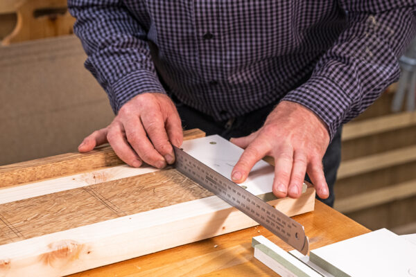
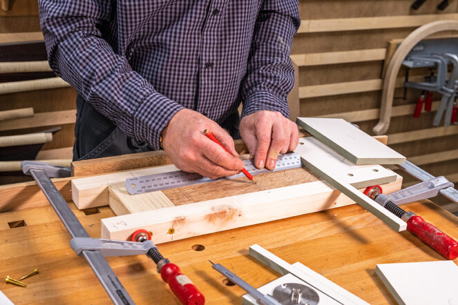
Mark out on your side pieces the positions of where all other pieces will join - the top, middle shelf, and bottom shelf and legs. Then mark the positions of your mortices.
Make a routing jig
Next, make a simple jig to help cut the mortices using a router cutter. This jig will help make the cuts repeatable and accurate. This is useful if you wanted to make more than one clock.
Top tip: Before doing this, ensure your side panels are cut to equal length and the ends are square and your mortices are measured and marked accurately.
Make a simple pine frame to fit firmly around one of the two uprights sections. This is glued and screwed together. It is important that this is made accurately and square.
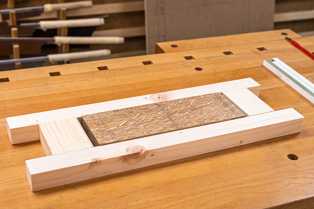
Next, you will need to attach sections of MDF cut accurately to size and positioned in place on the framework. These will act as the routing guides.
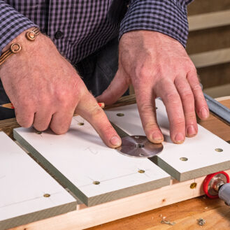
We are using a 14mm guide bush and 10mm cutter with the jig to cut the mortices. This leaves 2mm offset either side of the cutter. Two steel rules will create the correct offset of 2mm from the edge of the cutter to the outer edge of the guide bush. The rules line up with the top edge of the mortice at the top of the clock. Accuracy is important at this stage; a shooting board ensures the ends of the MDF are square. This is screwed to fix into position.
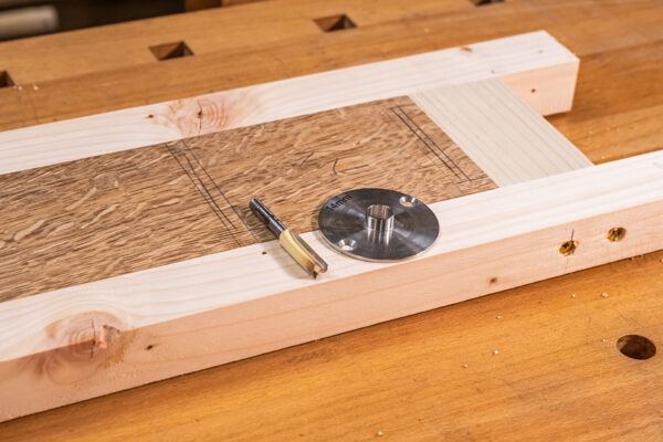
A strip of the same thickness MDF is cut to the same size as the guide bush (14mm). This is placed alongside the first piece. Measure from the edge of this to the next mortice location and the then remove 2mm off this. Cut the next piece of MDF to this measurement and fix this in place. Move the spacer along and repeat this so that four MDF pieces are fixed in place.
The guide bush will fit into the slots easily. To ensure the correct length of the mortices is cut, start and stop blocks are now added. These are set 2mm off the marked-out mortice and screwed to fix it in place.
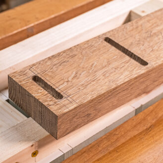
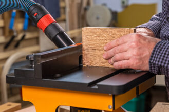
Cut the mortices
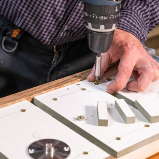
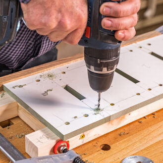
Load the guide bush and cutter into the router and position the router in place on the jig before turning on the power. Lower the cutter onto the work, and then set the depth stop to allow a 12mm depth of cut. Check the position of the upright clock section in the jig. Extraction is important for this. Use the router as a drill to create a series of holes, then, work back and forth. The waste will need cleaning out as this will collect in the slots. Double check the slots.
Repeat this process for both upright clock sections.
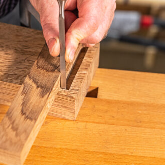
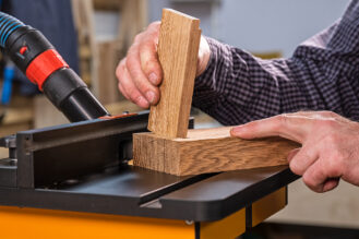
With the three mortice holes cut in each upright section, the ends will need squaring up with a chisel. Measure the depth of the mortices with this and work out the overall length of the cross rails. These rails can then be cut to length.
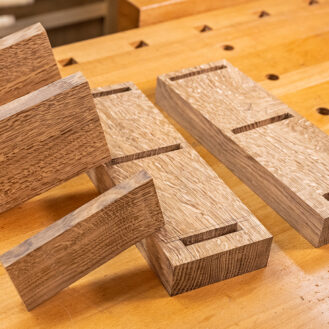
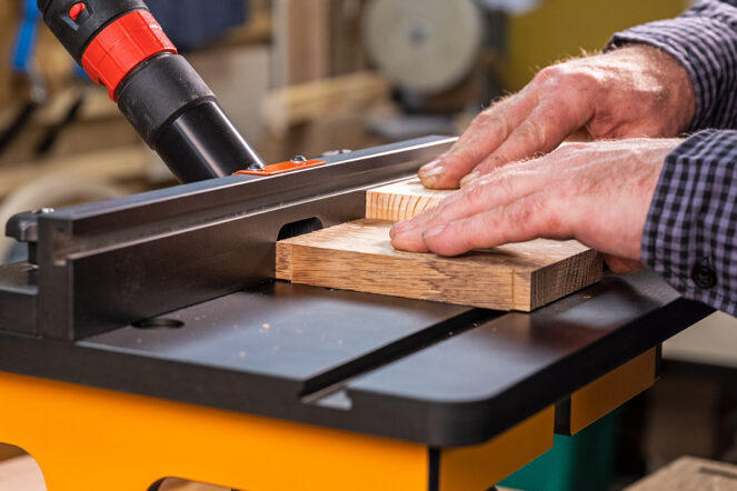
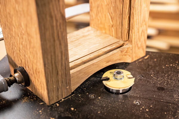
Cut the tenons
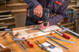
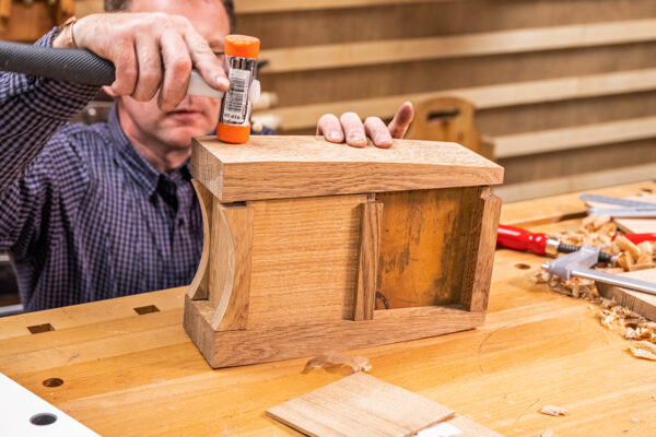
Using a router table set up with a milling cutter, cut the tenons on the ends of the rails. These are all slightly different so take care to ensure the correct face is machined. Use a push block behind the rails to support the workpiece whilst pushing through the cutter. Take several passes to remove the material, as this will be more accurate. Assemble the frame ensuring the joints close up.
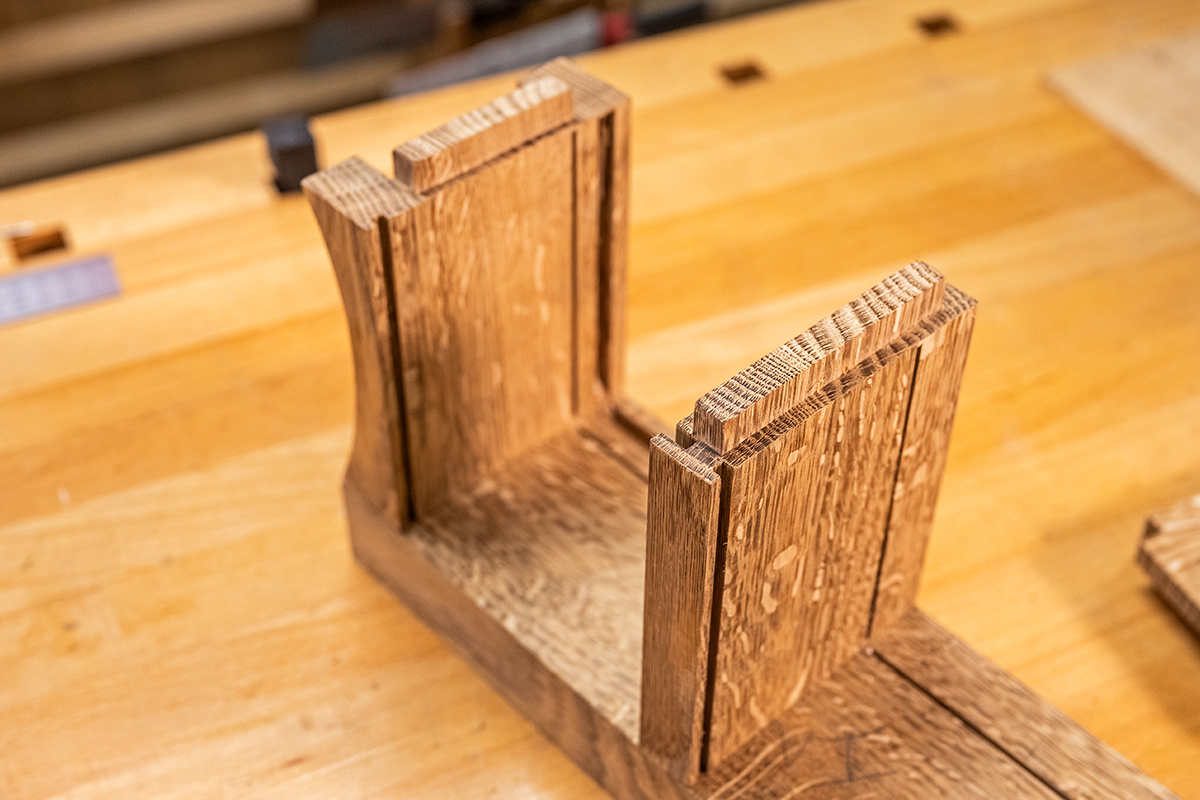
Fit the rails
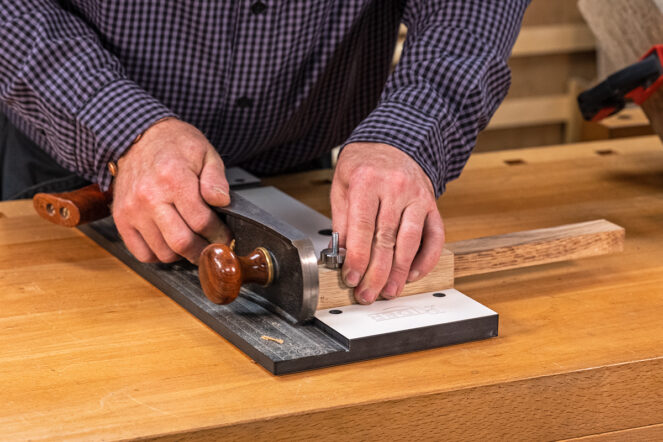
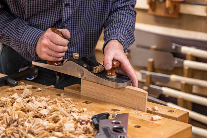
With the frame assembled, measure the length of the base curved rails. Ensure the end of the rail material is square by using a shooting board. Cut just over length and then use the shooting board to accurately fit. Two are needed, front and back. The curve can then be added. Cut out and shape with a spokeshave.
Glue the curved rails onto the bottom cross rail. This is best done with the carcass assembled, to ensure this is in the correct position. Clamp in place and leave to dry.
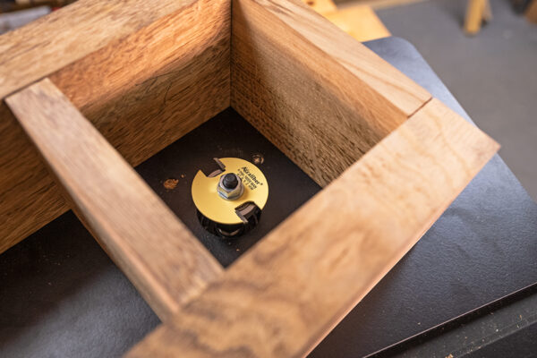
Create the panel grooves
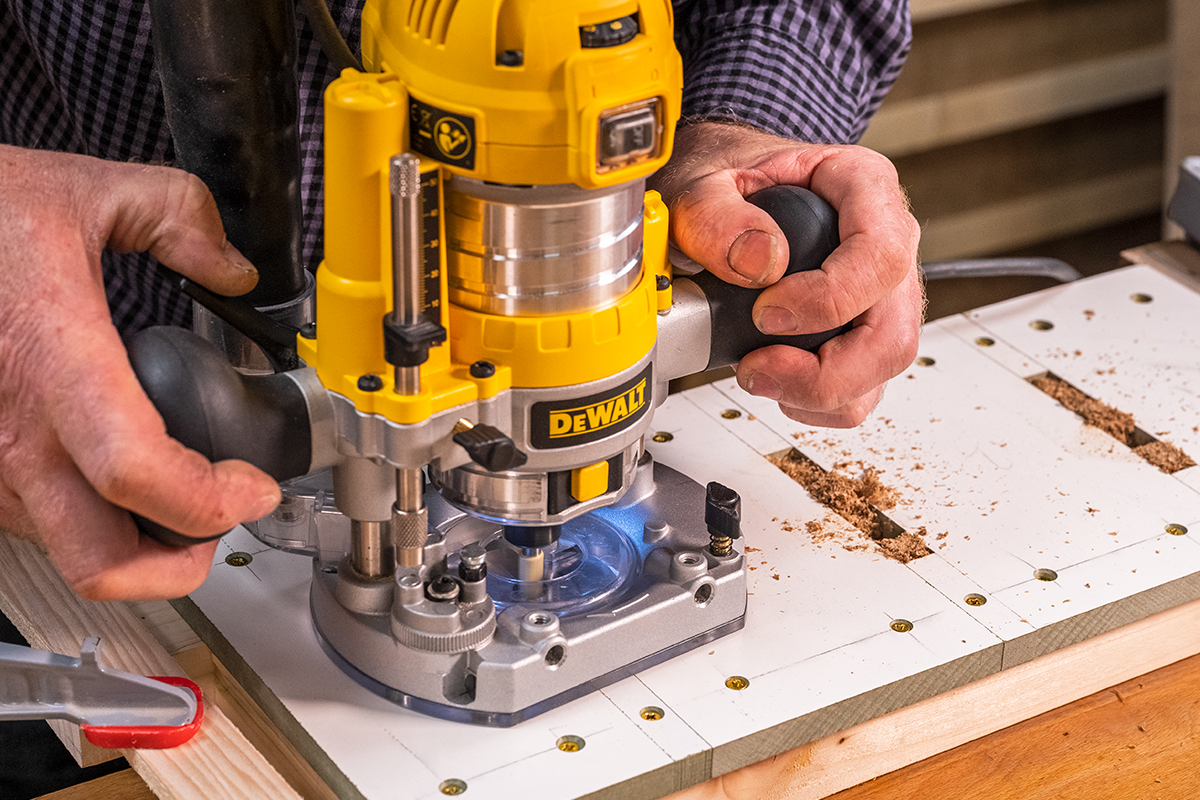
Next, cut the grooves to hold the copper and wooden panels. Top tip: A slot cutter set provides more strength than a 2mm straight cutter, as it has a bearing fitted below the cutter to create a 6mm deep groove.
Cut the groove to hold the brass first. Set the cutter 25mm up from the table. Clamp the carcass to hold this together whilst cutting these. Place the workpiece face down with the top section over the cutter, in the middle of the workpiece. Then slowly move the workpiece around cutting a groove in each edge.
Then add another slot cutter ensuring the teeth line up. This will create a wider groove in the lower section to hold the wooden panel. Check the widths to ensure the panel material will fit in. Adjust the cutter height to adjust the fit.
The back of the cross rails has a groove cut to take a panel that is removable. These are set at different depths. The underside has a 6mm deep groove and the top face is 3mm deep. These can be run along the fence of the table,
Square up the end of the grooves using a chisel. The narrow 2mm groove can be done with a small carving tool and the wide groove with a standard chisel.
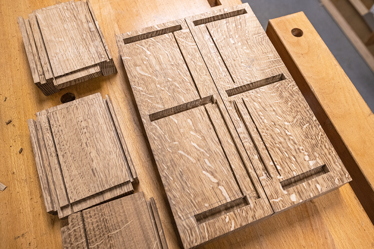
Cut the wooden panel to fit in the lower section. Use the shooting board to adjust this so that it fits in nicely
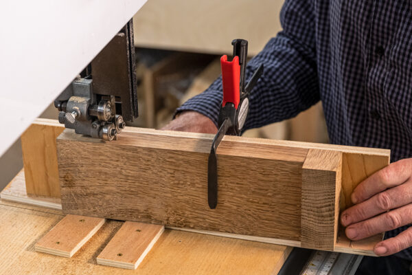
Shape the uprights
Next we can cut the upright side sections to feature a curved shape. To make this repeatable, a simple jig was made to carry the upright through the bandsaw. The jig has the curved shape on the edge which runs against two pins that are located on a board that is fixed to the table of the bandsaw.
The work is clamped in place and slowly feed through the blade. It's 100mm deep oak, so take a little bit of time. The clamp will need moving as the cut progresses. The two uprights together to show how accurate this is. These are then cleaned up with a flat spokeshave.
Fit the backs
To fit the back, place in the deeper groove and then drop down into the 3mm groove. These can be adjusted using a shooting board to fit. The top edge will need a chamfered edge to allow this to slide up into the 6mm deep groove.
Cut the top to length, but leave over width, as cutting cross grain will create a little bit of break out which can be cleaned up later. Mark out the chamfered section. The waste can be removed in a number of ways. We used a shoulder plane with a block clamped along the cut line. The edge of the pine block was planed to 68 or 22 degree angle and the shoulder plane run along to create the chamfer. The front edge is then planed square and cleaned up before the piece is cut to width.
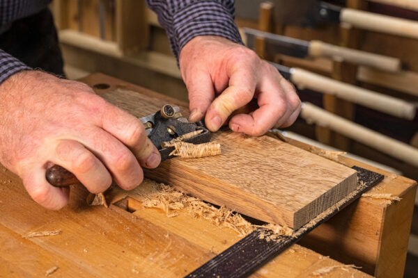
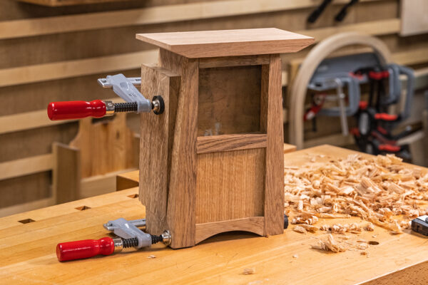
Cut the brass panel and dry fit clock case
The copper insert can be cut on a bandsaw using a premium blade. Measure the size, set up the fence and cut. Should the copper need squaring up then the shooting board can be used - it will take the edge off the blade, but it will cut the copper.
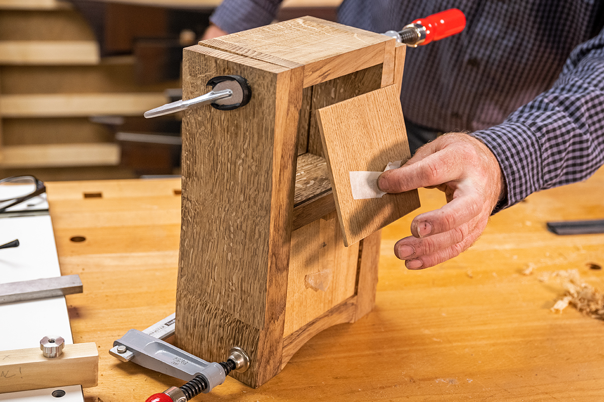
Dry assemble by inserting the copper and the panels. The off cuts of the upright are in place to help clamp this square. Check everything comes together, ready for the cutting of the clock face and the decorative wooden panel.
Read our Decorative Clock Face and Panel blog to learn how to make the copper insert and panel.
Made it? Share it!
If you have made our clock case project, then why not share your images with is via social media? Tag us @axminstertools on Facebook and Instagram.
If you have enjoyed making this project, then why not take a look at how to create decorative face and panel inserts with Ben in part two of this clock project.